
There’s a lot of confusion about the different types of battery that you can find in Sprinter vans, and how to go about connecting to them in order to power things inside the van. Here are some photos to help make things clearer.
WARNING – before you go messing with any of the connections in this article, unhook the battery connection (just to the right of the accelerator pedal) and if you have an aux battery, unhook the positive or negative connector from the aux battery itself.
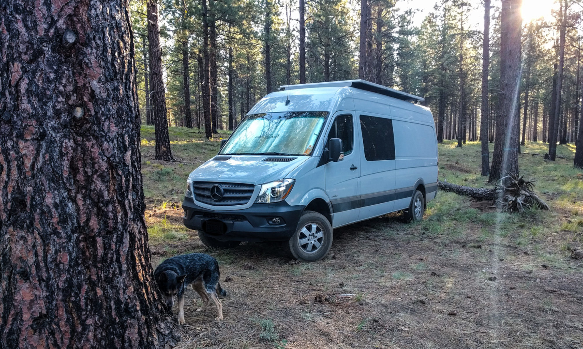
WARNING #2 – these photos are from a 2015 NCV3 2500 Sprinter van with a factory-installed aux battery. Your van may be very different.
Starter (engine) battery connections on the Sprinter
If you don’t have an auxiliary/additional battery package (no extra battery added by Mercedes under the hood, or under the passenger seat) then the only place you should really get power from is the special set of connectors made for that purpose. You’ll find them under the driver’s seat. This set of connectors is called the “X145 Terminal.” It’s option EK1, so it’s often referred to that way too.
The X145 terminal is mounted on the top of one of the rails that goes from left to right across the top of the seat base. In the picture below, I’ve already unclipped the terminal cover, which is now hinged up and away to the left.

- On the left is a stud with a blue/yellow wire. This provides power when the engine is running (Terminal D+). It has a 10A (120W) maximum current draw.
- In the middle is a stud with a red/grey wire. This is a direct starter battery connection (Terminal 30) so it’s live all the time. It has a 25A (300W) maximum current draw.
- On the right is a stud that provides power during ignition (when the key is in but the engine isn’t running). It’s got a black/yellow wire (Terminal 15) and it’s a 15A (180W) maximum current draw.
You might be able to reach this terminal by sliding the driver’s seat all the way forward and removing the board that covers the seat base. Better still is to completely remove the driver’s seat. It’s only four bolts (the seatbelt can stay attached if you just move the whole seat toward the front of the van).
CAREFUL: undo the wires that thread through the seat base cover board and up to the seat before you remove the board. Reconnect them before you reconnect the battery or turn the key in the ignition. If you don’t you’ll get error codes that can only be reset with a diagnostic tool.
Any wires you connect to these studs need to have their own fuse. The fuse should be rated for the wire diameter and length, not for whatever you’re attaching to the other end.

Even if you do have an aux battery, you might want to make use of these terminals. For instance, we have our electric door step hooked to Terminal 30 so it always has power from the engine battery. That way, if we ever have to take the Aux battery out (or if we run it down unintentionally) the door step will still work.
Auxiliary/Additional batteries
If you have a factory option package that added an auxiliary or additional battery, you’ll have an extra battery under the hood, or maybe under the passenger seat. This second battery should be of exactly the same type as your starter battery (the one under the driver’s feet).
The aux battery works by connecting to the alternator and the starter/engine battery whenever the engine is running, and then disconnecting whenever the engine is off. This way, you can power some electrical devices without running down your starter battery. You’ll always be able to start the van and drive.
It does this by using a relay under the driver’s seat. It’s the big black box to the right of the picture with the two copper bars going in to it.

The red cable at the front is from the starter battery. The other cable goes to the aux battery.
You do NOT want to connect any additional electrical devices to the bolts on this relay. There’s a special hook-in point for the auxiliary battery. It’s also under the driver’s seat. On the more recent models it’s at the back of the driver’s seat base.

You can attach an additional cable to the connectors inside this box. The cover of the box unclips for easy access. Just squeeze the tabs in the middle.
The red cable comes from the isolator relay. The black cable goes to the aux battery in the engine compartment. Don’t get fooled by the cable colors. The black cable is still positive rather than negative.
We chose to use a secondary fuse panel for all the electrical items we wanted to attach to the aux battery. The Blue Sea Systems ST Blade fuse block with a negative bus gave us everything we needed. It has a cover so the terminals aren’t exposed, and it uses the same style fuses as the rest of the van. Our aftermarket electric seat heaters are attached here, and we’ll probably attach a subwoofer to the fuse block later too.
Having the negative cable on the same fuse block makes it much easier to terminate wires here. There are a couple of points to connect the negative cable to inside the driver’s seat base. Just find the clusters of brown wires where they’re bolted to the metal of the van. You can just see one of those clusters in the picture above (bottom left of the picture).

We ran the wires for this fuse box to the outside of the driver’s seat base. We attached the fuse box to the back of the driver’s seat base where it’s tucked away but still easy enough to access if we have to change a fuse.
Note that the supply cables for our fuse panel are pretty beefy. We had some 2AWG cable left over from our full electrical install so we used it. It might have been overkill, but you could have some pretty serious power running through the cables if you hook up all the fuse positions .
Blue Sea also make 12-circuit versions of this fuse block if you think you’ll be running more devices from the aux battery. Be careful though. It’s only a 95 Amp-hour battery, so you can run it flat quite quickly if you attach a lot of electrical consumers to it.
If you want additional information about how the aux battery works, take a look at the Retrofit guidelines for auxiliary battery in NCV3 Mercedes Sprinter. It shows the location and function of each of the components.
Love your website. Very informative, well written and with good photo documentation. I do have a specific question relating to the factory aux battery relay. You recommended not connecting any electrical consumers to the relay directly. I have a situation where I want to do this, and I think it would be fine, but I am interested in your thoughts. I have a 2016 crew van with the factory auxiliary battery installed. I am upgrading the audio system. I am actually doing the speaker upgrade as you did, but additionally I am adding an aftermarket amp and sub amp as well as a subwoofer and equalizer. Normally, with this configuration, you would connect both amps to the starter battery with 4 ga cable and a 100 amp fuse. However, I want to take advantage of what the auxiliary battery was intended for, to power additional components without drawing down the starting components. In this case, playing the radio while parked in a campground or at a outdoor flea market. The 30 amp connection under the driver’s seat works fine for small consumers. (I like the Blue Sea fuse block that you used) However, the 30 amp limit will not work to power my amplifiers. You say the charging circuit to the aux relay is 100 amps. I think this would work fine for my amplifier connection. Although the circuit is protected by a 100 amp fuse, the absolute maximum both amps could ever draw together is probably 50 amps, and the average consumption for both together is listed as about 8 amps. I would appreciate your thoughts on using this relay connection for the amplifiers. (100 amp fuse would be within 6-12″ of the relay.
Thanks!
Greg
Hey Greg, for your use that sounds fine. Like you say, this use is very much what the aux battery was designed for. Remember that you are fusing the wire, not the components when you choose fuse size.
If I were to want to add solar where would
You recommend to connect the output of the solar controller to the battery? At the Aux battery mounting points you described?
Hi Michael,
Without knowing the amount of solar you intend to add, and whether it’s going to the standard aux battery or to an upgraded size battery, it’s hard to give you specific advice.
If you connect to the aux battery terminal (distinct from the EK1 terminal), then the solar will only charge the aux battery and not the starter battery while the ignition is off. That’s probably what you want to happen.
Unless you had a really, really large number of solar panels, the cable size at this point is sufficient to take the solar charge current.
Old post but gonna give a try.
Hi Dieselfumes, like Michael, we’d like to plug the solar directly (but from the charge controller of course) into the (100A Led) factory auxiliary battery through the hooking point (I am a bit confused since you used the term Terminal in your answer) under the driver seat. Using the plus pole on the hooking point, the negative going onto the chassis. If I understand correctly, it is possible and indeed, we want the solar to only charge the aux battery when the motor is off. We’d have 2x100w panels in parallel and a 30A charge controller. Cables from the charge controller to the hooking point are 4mm2 (Europe here). Just asking if we’re correct …
Mercedes calls it a terminal, so that’s the terminology we use too!
We’ve never tried to hook things up in the way you describe but theoretically this should indeed charge the aux battery when the engine is off. When the engine is on, your solar will be “contributing” to the whole circuit (aux battery, engine battery, any loads).
The cable size from the charge controller should not be an issue. Those cables are sized for the current from the controller, and will be attaching to larger cables at the aux battery terminal anyway.
If you have the option, be sure to set your charge controller for the correct type of lead-acid battery. The aux battery is most often sealed lead acid but may also be AGM.
First thank you very much for all you amazing work. We have the automatic Sprinter step for our side door. I would like to put a switch on it so I can leave the step out when we are camping. It takes the battery down and is annoying.
Hi, is your step the OEM Mercedes version or an aftermarket one? If it’s the Mercedes version, it might be hard to add a switch without causing the vehicle to get upset.
As far as I know, the OEM step is controlled by the Parametric Special Module (PSM) and so it reads messages about the doors being open or the ignition being on from the CAN bus and then tells the step whether to extend or retract based on these messages.
It’s probably possible to find the wire that brings power to the step and put a switched relay in that circuit, but it might cause the van to throw an error code if it tries to retract the step and nothing happens.
If it’s an aftermarket step, you can almost certainly add a switched relay to the power circuit feeding the step.
To be honest, I’m surprised the step takes enough power to draw down your battery. Are you sure it’s the step, and not something else that’s attached to your starter battery while you are camping?
My 2014 sprinter van has the PSM…with 200 amp batteries. My van has been sitting outside while it is torn apart. Is there a way to keep my OEM batteries charge….Would you recommend on of those window solar charges? Thanks Again. Have a happy new year!!!!
Melanie
If you aren’t using the van, you could just disconnect the batteries. They will keep their charge for several months. I’ve not used any of the solar chargers for stock batteries, so I don’t know how good they are. You could ask at the Sprinter forum.
You say that you have 200 Amp Hours of batteries. If those are stock batteries, I’m assuming you have the auxiliary battery and the starter battery installed (each one is 100 Amp Hours).
When you are camping, you should only be using the auxiliary battery, not the starter battery. The two cigarette sockets that come from the aux battery are the one on the driver’s seat base and the one in the back door pillar. If you use any of the other cigarette sockets, you are in danger of running your starter battery down. Then, you wouldn’t be able to start the van. That would be bad. So, really, you have 100 Amp Hours of battery for camping, which means 50 Amp Hours of usable charge because you should not run the battery down beyond 50%.
That’s one reason why the auxiliary battery isn’t particularly good for van conversions.
Melanie, there’s a thread on the Sprinter forum that talks about the wires for the stock electric step, and which fuses to pull to stop it working. Knowing that information you could probably get it to switch off in the extended position. You’d have to be really careful not to drive away with it extended though.
Wow. Your site,is awesome. Glad I stumbled upon it.
I have a very basic question about running power off the blue Sea fuse box. I plan to run some minor components off a fuse box (lights, fan).
If I understand correctly you ran a + 2awg wire off the aux connector + post to the fuse box and then ran a – 2awg wire from fuse box to the grounding under the seat. Did I follow that correctly?
Did you also run a Mega Fuse (instead of the copper strap) across the connectors under the seat?
Do you think it is a good idea to run a kill switch between the connector posts and fuse box?
Thanks in advance.
Tim
Thanks Tim!
Yes you’re right about the wire gauge and where I attached the positive and negative cables. I used 2AWG because it’s what I had lying around. Depending on your loads, you may choose to use a different wire gauge.
I did not run a mega fuse, but I should have done and will do next time I have the seat off.
A kill switch is an awesome idea. That way you can isolate the entire fuse panel very quickly in an emergency. We are’t using the Blue Sea fuse box as our primary power source, so I skipped that step.
Hi!
I have an auxiliary battery from Mercedes in my 2018 sprinter. I’m working through trying to wire up a secondary fuse panel for lights and other low voltage accessories from the terminals underneath the drivers seat. I ran 4 awg to my blue sea fuse box. However, I’m not getting any current when I put my volt meter to the terminals. I checked the auxiliary battery under the hood and it is showing that it has current. Is there a fuse I need to add to complete the circuit? I’m really not sure where to go from here since I’m not getting any juice to the terminals. Thank you so much for your site and information. It has been extremely helpful.
George, depending upon which terminals exactly you hooked the secondary panel up to, you might only get current when the engine is running. If you used the special hook-in point for the aux battery mentioned in the post above, you should be OK. There are no extra fuses. That aux battery hook-in point should always be live.
Just remember, even though one cable in this hook-in is red and one is black, both are actually positive (the black one comes straight from the aux battery positive terminal). Make sure your secondary panel’s negative terminal is properly grounded to the chassis or to a grounding point under the driver’s seat (where the bundles of brown wires are bolted down).
If you connected your 4AWG cable to the relay, or to the EK1/X145 terminal, then (1) you may have connected to a switched power source and (2) that’s a bad place to connect your fuse panel.
Hi dieselfumes, any idea what is the negative bolt/lug size under the seat?
Tom, it’s been a while since we were under the seat. From memory, I’d say around M5 but I really don’t know. If you slide the seat all the way forwards you might be able to reach it to find out.
Hey dieselfumes (and Tim),
Curious what size fuse you will use for Mega-Fuse? 100 amp?
I’m setting up same fuse block with 4AWG and will be running ARB fridge periodically.
Thanks for all your documentation.
Phil
I ended up using a 100 amp mega fuse.
Hey Phil, I’m trying to work that out. If I was just fusing the wire I’d added, I’d use a cable calculator based on the AWG and length of the wire. The thing is, the fuse is in-line with the (1 AWG?) factory cable to the aux battery. I would need to measure the length of that cable and fuse it appropriately. Then, the fuse might be too big for the wire I added. So, I may just end up fusing the cable I added rather than/as well as adding a mega-fuse.
UPDATE: Looking at page 6 of the battery retrofit guidelines document I linked to in the post, it’s pretty clear that the wire that runs from the main starter battery to the aux battery via the relay and the electrical connector is already fused with a 150A fuse at the starter battery. So, if you’re adding a fuse, you need to add it on the branch you take off this connector rather than across the connector terminals.
In other words, you need to bolt a fuse on to the electrical connector, then bolt your cable to the other side of this fuse. Of course, you might put a kill switch in the circuit first.
Doing things this way just seems right to me. Now you don’t have to worry about the length of the aux battery cable. You just have to worry about the length and gauge of the cable you use to connect from the electrical connector to your fuse box (and back to a grounding point).
If the aux battery cable shorts out or bad things happen to the aux battery, the 150A fuse at the starter battery will blow. If bad enough things happen to your additional fuse box, that 150A fuse will also blow. But before it does, the properly rated fuse that you add to your fuse box cable will cut out first.
Adding a fuse to replace that copper bar doesn’t help protect your additional fuse box. If you rate that fuse correctly for your additional fuse box, it’s likely to be undersized for the supply from the starter battery to the aux battery. And it wouldn’t stop your additional fuse box from being supplied by the aux battery, even if it blows. It would just take the starter battery out of the equation (there’s a battery on either side of the electrical connector).
Thanks for the response gentlemen. Yes, it’s a guess when estimating the length of the cable from aux battery to relay…probably 6-8 feet. My run of 4AWG is 5-6 feet. Considering my potential loads, I think I’ll start with a 50 amp fuse. Would rather be wrong with only a melted fuse.
Thanks again for all your advice.
Phil
Hello….Thank you so much for all of the information in these posts. I feel that I am learning so much. My husband installed two maxair fans on the roof of our van. We would like to wire them through the auxiliary battery connection as described. We are waiting to receive our BlueSea fuse box. I think I understand about connecting a positive wire to the auxiliary connector post under the driver’s seat and running it to the fuse box….and then run a negative wire from the fuse box to a ground.
My question is about where we would place the Mega-fuse….and what size fuse. And where would we place the kill switch on this set up? And, any recommendation on brand of kill switch?
You can probably tell by my questions that I am just learning about this stuff…and Dieselfumes…you have my utmost respect for your van build….and mostly for your patience in posting so much information and in so much detail. Thank you taking the time to share your knowledge with everyone.
Teresa and Luis Rauda
Hi Teresa,
There is a copper strip inside the auxiliary battery terminal where you’d connect your fuse box. It is bolted between the two posts in that terminal. Some people replace this copper strip with a Mega-fuse. We have not done so yet.
The reason we haven’t is because it didn’t come with one from the factory. I think that the fuse Mercedes installed at the end of this wire is probably sufficient. If you want to add one, that’s fine too. It won’t hurt anything and it might help.
What you will need is a fuse on the wire that you use to connect from the auxiliary connector post to your fuse box. You can calculate what size of fuse by adding up the positive wire distance from your auxiliary connector to the fuse box and the negative wire distance from the fuse box to ground. Once you know that, and the maximum current (amps) you would ever pull through the fuse box, you can use one of the online wiring calculators to work out what size wire and what size fuse to use.
As for the type of fuse, these Blue Sea 5191 fuse block terminals are very compact. Remember to order the right size fuse too. The one problem with these fuses is that they aren’t as common as other types. If one was to blow, it might not be something that local stores stock. However, because you’re basically fusing a fuse box, something pretty bad would have to happen for this fuse to blow.
You also asked about kill switches. It’s probably best to put this switch in a position that lets you easily change fuses when it’s “killed”, so it would make sense to put it in the circuit between the auxiliary connection and the fuse. That does leave a very short section of wire unprotected by a fuse, but that should not be an issue. As for brand, I really like the Blue Sea stuff. Their M-series switches are sort of overkill for your needs, but they are very well made. People sometimes mount these through the side or rear of the seat base so they can easily reach them. There’s no way you’d accidentally knock this thing on or off. It has a very solid “clunk” when you switch it.
You say you’re just learning about this stuff, but you’re asking good questions. Remember: I’m not an electrician. I had to learn this stuff too. There might be some other folks out there who disagree with what I’ve written and what I’ve just told you. However, if you keep reading and learning until you are confident that you know what you’re doing (rather than just copying something blindly) then you should be just fine!
Enjoy your fans, and enjoy your van. If you just cut two massive holes in the roof of the van, everything else you do will be easier from now on.
Thank you so much for your quick reply. The information you provide is more than helpful! I, too….am not an electrician! But I can learn! Yes, it took nerve to cut those holes in our van (2015 Cargo van)….Not only the holes for the fans….but big holes for windows on both sides and rear doors. Our van is definitely a work in progress…..Your write-up keeps my husband and I up late at night—reading and re-reading. We are in awe! Again—-we can’t thank you enough! Teresa and Luis, Apple Valley, CA.
First off, great blog. I’ve got a question regarding the aux battery system. We installed a max air fan and planned on hooking it up the factory aux battery system. We swapped the factory connection point with the same fuse box you have pictured above. When we connect our wires to the fuse box…nothing. In order to make sure the fan worked, we used jumper cables and connected them to our aux battery direct to ensure our wiring was correct which it was. Anything special that has to be done to the system before using it? Or recommended trouble shooting? Next step is going to be to check the cut off relay to make sure there aren’t issues there. Any tips or suggestions would be greatly appreciated
Thanks
Dan
Hi Dan,
Good job troubleshooting by jumping directly to the aux battery. That narrows the problem down to the fuse box you added.
When you say you “swapped” the factory connection point, what do you mean? Hopefully you didn’t change anything in the stock van wiring setup. All you should do is connect the positive wire that runs to your fuse box to this connection point (on the bolt that the black wire is connected to) and run the negative wire from your fuse box to one of the bolts under the seat base that has brown wires attached to it.
You also need to insert a fuse in the new fuse box for the circuit you connected your fan to, and make sure you have your positive and negative wires connected the right way round. Check that the fuse is good (not blown).
It’s very unlikely that the cutoff relay isn’t working, because your aux battery had enough power to run the fan. Even if it wasn’t working, the power coming from your aux battery would still drive the fan if all your other wiring was correct.
Hopefully that doesn’t sound condescending to you – I am just worried that you did something like wiring the fuse panel in line with the aux connector, or removed the copper strip between the two bolts in the aux connector.
If you can’t figure it out, send me an email with a couple of photos – dieselfumes [at] this site’s domain.
Thanks, so if Im understanding you correctly, the original factory tap in point shouldn’t be removed. What you’re saying is you connect your fuse box to that positive lead, and then ground the negative side to the floor?
Yes, that’s correct. The copper bar across the tap-in point connects the starter battery to the aux battery, so removing it means your aux battery won’t get a charge!
The circuit is [Starter battery] -> [Relay] -> [Connector (with copper bar)] -> [Aux battery]
What you are doing is tapping in to that circuit at the connector point. It’s a great location because when the engine is on, you get the power straight from the starter battery. When the engine is off the power comes from the aux battery. (the reality is slightly more complex than that, but it’s a good enough concept for this conversation).
Your new fuse box positive wire connects to the aux connector without removing the copper bar. Your new fuse box negative wire connects to one of the existing negative posts on the floor. There are two under the driver’s seat. Just find the bundles of brown wires that are bolted to the floor, and add your connector to one of those bundles.
Let me know if that works for you.
Diesel,
It worked exactly as advertised, thanks for the help.
Hey Diesel, Thanks for the hours and hours of info you have given us , incredibly generous. My question , alittle off topic do you have a diagram for your wiring of the entire van somewhere online?
Hey Mike, thanks for the comments. We did’t put our wiring diagram up online. We might do in the future, but the big issue is nobody should ever blindly copy what we did without understanding why we did it. If we put the diagram up, other people could get themselves into trouble.
Hello Diesel…..This is Teresa, again! We are trying to connect two MaxAir fans to the auxiliary battery connection. When we disconnected the Auxiliary battery (by the gas pedal)…..the black cable going to the Auxiliary connector still has 12V running and the Aux. side had zero. Does this mean that the black cable is from the starter battery?
Also, is there a reason that we should NOT connect anything to the aux. bolt on the relay?
I am trying to figure out what we are doing wrong. Please help!
Hi Teresa,
The disconnect by the gas pedal is for the starter battery. Like you found out though, even with that disconnected the Aux battery is still attached to its side of the isolator circuit.
When you are looking at the auxiliary connector, the black cable is the Auxiliary battery side, the red cable is the isolator/starter side. That’s why you still had voltage on the black cable. If you trace the black cable, it goes all the way to the engine compartment and it’s attached to the positive terminal of the Aux battery.
The easiest way to kill power from the Aux battery is to undo the brown cable on the negative post of the battery (or undo the other end where it bolts onto the metal of the engine compartment).
Mercedes says to use the Aux connector, not the relay bolt. There is no reason to use the relay bolt. It’s not the solution to the problem you thought you were having.
Remember that you’ll need that piece of copper installed between the red and the black wires in the Aux connector because otherwise current won’t flow from the starter battery to your Aux battery and so the Aux battery won’t get charged.
Hope that helps!
Hello Diesel….THANK YOU, THANK YOU, THANK YOU!!!
We actually took our van to an automotive electrician because we did not feel confident enough to tackle the electrical connections ourselves—-Well…..after having read so much about how the connections SHOULD be done by reading your posts….I was disappointed by the work done by this so called specialist!
But….after reading and re-reading your posts—-and after watching what the electrician had done—-I felt confident that I could undo the connections that were made and do it the right way (Your way)—-MYSELF! And, thanks to you—and only you—we were successful! I would like to send you a personal email rather than post on this site. Can you please send me a personal email at: [xxxx]
Again, Thank you , Teresa and Jose Luis Rauda
Great website. Thanks. I have a 2015 2500 sprinter crew with the factory auxiliary battery under the hood. I have been powering an Engel refrigerator/freezer with it 24/7 for the past 30 months and I think I may need to replace it soon. Do you know if I can replace it with a 12 Volt, 125AH AGM Deep Cycle SLA Group 31 battery such as the one I have linked to below? Thanks.
https://smile.amazon.com/GOAL-ZERO-Yeti-BATTERY-UPGRADE/dp/B00ISDL05K/ref=sr_1_fkmr0_2?ie=UTF8&qid=1493241383&sr=8-2-fkmr0&keywords=goal+zero+1250+replacement+battery
Or are you aware of something that would work better?
Martin,
As you’re probably aware, the reason you need to replace that battery after 2-1/2 years is because you’re working it really hard. It’s not really designed for deep discharge like the usage pattern you’ve got. The AGM deep cycle batteries would be better for your needs. But there’s a catch.
Mercedes recommends using the same make and model of battery for the starter and the aux. That’s because they are on the same charging circuit. If you used different batteries, they’d have different charging profiles. One might overcharge or the other might never completely charge.
Some people do replace their aux with a different type of battery. I wouldn’t recommend it without also adding a DC-to-DC battery charger like the Sterling brand ones. Those are not cheap.
Additionally, I’m not sure I’d buy a Goal Zero battery unless you’re sure you’re getting a good price. That company seems to have a premium pricing strategy, and it’s not clear that their batteries are necessarily very high quality. There are several well-known battery brands to choose from instead. I have no specific recommendations.
I may be late to the game… new to owning a sprinter… I have a 2015 with the e28… and maybe I am over thinking this… I see where to attached the red wite for the inverter in the click off the top box… were do you put the negative terminal to return to the aux battery? can i use the cluster of brown ground wires? Am i slow on the up take? Did I miss something?
Just undo the bolt that holds the brown ground wires to the chassis, add your wire to the set, and tighten the bolt back down again. The Aux battery uses the same common negative feed as the rest of the vehicle, and that negative path is through the chassis.
If you look at your aux battery under the hood you’ll see a fat brown wire from the aux battery negative terminal that bolts on to the metal of the van body just above the driver’s side front wheel inner fender. That’s where the connection “exits” the chassis metal back into the battery.
Trying to find out where the fuses are for the ek1 or X 145
Brad, according to my wiring diagrams from a 2007 model year Sprinter, the X145 fuses are #1-#3 in block 55/4. In human terms, that’s the top row under the driver’s seat. They are fuses labeled 10-12.
The red wired always-on connector (Terminal 30) is fuse 10, 25 Amps.
The black and yellow wired connector (Terminal 15) is fuse 11, 15 Amps.
The blue and yellow wired connector (Terminal D+) is fuse 12, 10 Amps.
Thanks for keeping up this incredibly helpful site!! I have a 2017 Sprinter Cargo Van that I am converting into an all electric, fairly simple, camper van. The van will have four 6v AGM batteries (448 amp hours). shore power, 4 stage 60 amp battery charger, and 2000W Inverter. Main electrical uses will be a few LED lights, the Westinghouse 600W microwave, the single ring Duxtop portable induction cooktop, charging my laptop, and the motor to raise/lower a Sportsmobile Penthouse top. No refrigerator or heater etc. Upfitting will be done by a local firm except for the penthouse top. My sprinter has the factory auxillary battery under hood but for simplicity sake, I am not thinking of tapping in to it. But what do you think??? Is it useful for anything such was jumping another battery, emergency power etc. (My general approach to camping is keep it simple–similar to most of the ideas on the site–like hooking up to power in friends’ driveways, etc.)
Hey there, Fred.
We didn’t use the aux battery for the conversion part of our van. Because it’s there, we ran a fuse box from it and used it for a couple of things like our aftermarket heated seats.
If you aren’t hurting for the space under the hood, then you might as well keep the battery in the system. Like you say, it might be useful for jumping the starter battery.
I will be adding a second battery to our 2011 Sprinter 2500. I have read the Aux Battery Retrofit Guideline.
I was hoping to use a Wirthco Battery isolator but wanted to make sure this would not cause issues with the Sprinter electronics associated with the alternator charging system
https://www.wirthco.com/batteryisolatorseries.html
I would be using the same type battery as the primary.
Any advice or recommendation would be greatly appreciated.
Thank You
Colin
Colin, I don’t feel qualified to give you advice about particular products that I haven’t had experience of or seen working in a Sprinter. However, the specifications of that isolator look like it would fit the bill. It’s slightly cheaper than similar products like the Blue Sea ACRs.
It has a pretty low resting current draw, but you might still want to put a switch on the thin negative cable from the device to turn it off if you leave the van for any length of time.
There is no reason why it should cause issues with the van’s electronics or the alternator. It’s not the type of system that is trying to trick the alternator into running when it otherwise wouldn’t. The alternator will just experience a heavier charging load.
This was my thought too. Thank you so much for your response! I really appreciate the input. Should I share the project outcome here? or is there a social media place?
Colin, feel free to post your results here. It’ll help anyone else who’s interested in using the same isolator.
Great…another question. I am pretty sure the 2011 Sprinter 2500 has the 180 Amp alternator. I was planning to us use the 150 amp isolator with a 150 amp breaker on the load (aux side) of the isolator. Is there a problem having a lower rated isolator than the alternator? As long as the breaker is there and the wiring is rated for the circuit…right?
Colin, the breaker and isolator should be sized for your load (the second battery plus any other items you put on that circuit), rather than for the size of the alternator.
Obviously the size of the alternator is important because it has to be able to power the items you add to the system, but that’s not what determines your wiring size or breaker size.
Because the isolator lets you combine the batteries so that you can jump start the van from your aux battery, you have to allow for that level of current too. 150 Amps should be sufficient.
If you do end up drawing more than 150 amps through that circuit, you’ve got other problems to deal with!
Ha! Yeah, it is kinda my intention to over build a little because the loads are are loosely defined so far. This van belongs to my local bike shop and they want to set it up to take to events and such. So, no cooking gear or camping kit to speak of. Thanks again. I will let you know how it works out.
Cheers,
Colin
This has been a great thread, I appreciate all the info. I’m in the process of installing an aux battery in my 2017 3500. I need to power a 12V Espar heater and a few LED lights. I ordered the parts from Mercedes as suggested in the retrofit guideline, the relay from MB cost $18 with the other parts bringing the total to $204 without the battery, is there an advantage of using a Bluesea relay, I lived aboard a boat for over 11 years and understand the value of Bluesea products. And is there anything I’m “missing” when I use the retrofit guideline? Thanks
Rick, the MB relay should be more than sufficient for a basic aux battery install. After all, Mercedes has installed it on countless vehicles. It’s what we have on our factory aux battery.
I don’t think it has the current rating that the Blue Sea products have. I *think* that my MB relay is 100A, but I don’t recall exactly. Also, with the MB relay there’s no option to push a button and use the aux battery to jump your van. However, that’s easily solved by clipping a booster cable from the aux battery positive terminal to the jump start terminal under the hood.
The Blue Sea products would be my choice if I was using a relay to power a larger house battery bank, although my preference would be to use a DC-to-DC converter with proper 3-stage charging profiles in that situation.
Thanks, I don’t plan on using the aux battery for much other than the heater and a few LED lights, I’m trying to get the van ready for a trip this April and heat is high on my wife’s list, we’ll be in Utah and nights can be cold. When I install the house batteries I will probably move the heater over to them, I just don’t have the time to do the house battery setup as that will have to wait until the fall.
You should be fine. Just keep an eye on the charge level of the aux battery. The Espar will run for a while with no problems, but for your sake it would be bad for it to decide the voltage is too low and cut out half way through a cold Utah night.
Thanks, the relay I just received from MB is not the proper one (looks nothing like the one in their picture more of a plug-in type than a connector). I’m going the Bluesea route for the relay, the question is there are several possibilities; fully automatic w/o a turn off switch (cheapest), fully automatic w/turn off switch on relay or (most expensive) the one with a remote switch with the off/on/automatic options, all are rated for high output alternators up to 120amps. Since the relay would be mounted under the seat manually switching off the relay would be more difficult vs going to the battery under the hood to disconnect one of the leads. Are you aware if any of these relays will cause problems with the computer? I get the advantage of the remote switch but at $176 vs $82?
Thank you for your help, I only have two weeks before we get “kicked out” of our rented condo with the heated garage.
Rick, all of the Blue Sea relays do pretty much the same job. Like you point out you are really paying for convenience when you get the remote switch that lets you switch the relay off or combine the two batteries to jump your vehicle. It’s just a question of whether that convenience is worth it for you.
I’ve not heard of any issues with the relays causing problems with the computer. It would be hard to see how they might interfere.
Make the most of your heated garage space – and good luck getting the build far enough along to be livable in your two remaining weeks.
Hi, I just purchased a 2018 4×4 Sprinter Cargo Van and I’m starting on the electrical. Your site has been very helpful. Kudos for a job well done. I had the factory aux battery installed and I was wondering what it powers when the engine is off?
Hi Mehosh, and congrats on your van purchase. The Aux battery powers the 12v outlet in the driver’s seat base and the one in the driver’s side D-pillar (by the rear doors). That’s it. There’s a relay that disconnects the battery from the rest of the system while the ignition is off. The starter battery is responsible for powering all of the van’s systems. The aux is only really designed to allow a deeper power draw while the engine is on.
Hi, I just purchased a 2018 4×4 Sprinter 144 and am starting on the house battery hookup. I am running two Battle Born Lithium batteries that will charge from a Zamp Solar 230 watt solar system, a Xantrex 2000w inverter/charger, and the alternator while driving. I was told to run a Sterling dc-dc charger from the alternator to my house batteries with a 40 amp fuse on both ends. One at the alternator (charging source) and one before house batteries. My question is can I pull power direct off of the aux battery under the hood to power the sterling charger or under the driver’s seat compartment or do I need to go direct to alternator?
Thank you for your time.
Matt, Sterling want you to keep the wires to and from their DC-to-DC chargers as short as possible. That’s why they suggest running the wire directly from the alternator. In the Sprinter though, especially if you have the aux battery, there are handy locations under the driver’s seat.
I wouldn’t pull power directly from the aux battery under the hood because that’s a very long cable run. It’s possible to pull it from the aux battery relay under the driver’s seat like it mentions in this post. Of course, you’ll have to calculate just how much current you’ll be asking the cables and the aux battery relay to carry. Those cables are around 1AWG.
Running a new cable directly from the alternator might be the best option in principle, but in practice it’s not always a neat approach. It depends where you’re planning on mounting the DC-to-DC converter. If you’re mounting it inside the vehicle, then I’d be tempted to use the aux battery relay as a power source. If you’re mounting it under the vehicle, you could run a cable from the alternator, from the starter battery, or from the aux relay depending on where your Battle Born lithium batteries will be hanging out.
Great site has helped out a ton with my conversion. Thanks.
I have a 2018 144 2500 4×4. I also have the factory aux battery option. I have wired in the same blue sea fuse box you have to my auxiliary battery connection under my drivers seat. I hooked up the positive to the auxiliary Positive point and the negative to the bolt on the body. I am currently powering three led lights and my max fan from this fuse box. I want to connect a 100w solar panel to supplement the charging of the aux battery. I just want to make sure I can hook up the charge controller to the same positive connection I have the fuse box hooked up to and still charge the aux battery and get power for my accessories. I plan to transition to a separate larger house system next year with a fridge and heater. Just trying to figure out the proper connection point for the charge controller to charge the aux battery
Andy, your plan seems sound. Connecting to the aux positive point under the seat means the charge controller for your panel will charge the aux battery when the engine is turned off.
The charge controller should sense the state of charge of the aux battery and only try to charge it when it’s low. It might get confused by the alternator voltage that flows to the aux battery when the engine is running, and so it might not try to charge at that point. But that’s not really a problem because the alternator is perfectly capable of charging the aux battery on its own.
D. Fumes~
Doing a simple 2nd battery install at interior rear of 2013 MB Sprinter 2500.
Made a very interesting thing under the drivers seat well.
What we discovered today, while going under the drivers seat for the 1st time, was that several 6 or 8 gauge red wires, one 2 Ga red, and a blue wire (6 or 8 Ga) were all made up into a bundle with the blue going to what appears to be a single fuse block attached to the floor at the center front of the space.
The output wire from the fuse block, also blue, has been cut off. Doesn’t look like copper strands either. Its location is where we think an aux battery connect would normally be but it doesn’t resemble any that we have seen photos of or reference to in any other Forum posts.
This bundle is all taped tight and is immediately above the channel entry point at the floor on the right side of the drivers well.
We have comment on your comments before. “RoadToad” is our user ID.
I am emailing this to you also so as to attach pictures, Don’t know how to do this otherwise.
Would really appreciate your take on this.
I got your email with the pictures. It looks like someone added wiring for an amplifier by hacking in to the cables in the van. You said that the blue wire didn’t look like copper. It is probably aluminum. Lots of cheap amplifier/subwoofer kits use aluminum cables because they are less expensive than copper. The fuse block also looks very much like the ones you get in these cheap kits.
So, I would suggest that this wiring is nothing to do with an aux battery install but instead was a stereo install. It’s probably wise to unbundle that chunk of taped-together wires and try to reduce the potential fire hazard. Unhook the starter battery connector first though!
Hi D – I have a 2014 sprinter w an OEM AUX. Can I use the OEM AUX battery cable that is hooked up to the relay and hook it up to dual 6V batteries? I would disconnect the AUX cable where it comes into the relay and hook that up to a battery charger/regulator.
I am thinking of using a charge controller like CTEK since it has the MPPT incorporated and I want to get a solar set up going too.
thanks for any ideas
Yes you can. But there are some things to consider. Really, it depends on how much you believe Mercedes when they say that you shouldn’t draw more than 40 Amps from the system, and also whether Mercedes’ cables are heavy enough gauge for your charging needs.
You didn’t say what size 6V batteries you were intending to use, or what current the CTEK charge controller draws. So long as the CTEK is pulling less than 40 Amps, you *should* be fine using that circuit. Other people have, and to my knowledge they haven’t complained about needing new alternators, or melting the OEM cables.
Thanks. I was thinking of disconnecting from that circuit at relay to avoid problems….But using cable. Also thinking of going lithium. How do those work under hood in old but not freezing climates ?
I think it would depend exactly what lithium battery you wanted to use under the hood. Different brands and different chemistries have different requirements.
Remember that even in cold-but-not-freezing climates you can still get windchill effects. Lithium batteries are normally happy being *discharged* even when it’s freezing. They just don’t like being *charged*. So if you were putting lithium batteries under the hood, you could just install a temperature-based cut-out relay to stop them from charging during times when that area of the vehicle was too cold.
Thanks D – Just reread your thread on Lithium batteries. More great info – thanks again. Trying to keep it simple, I settled on a 100ah LIFePO4 to place under the passenger seat. Will hook up with a Renogy DCC50S 12V 50A DC-DC On-Board Battery Charger with Solar MPPT. Disadvantages that I see of placing battery under passenger seat is loss of space for future Espar and my wife worrying that she is sitting on top of a lithium battery. Any other suggestions to consider?
That type of lithium battery (LiFePO4) is very different from the ones that Boeing had trouble with on their planes. If you look online, you’ll probably be able to find a video of someone shooting a bullet straight through one of these cells, with no flames to be seen. That might help with the convincing. Just one note of caution: while you *can* place them on their side, most manufacturers recommend putting LI batteries upright. So just be double-sure that you have the depth under the seat for your particular model.
I vaguely regret not putting my Espar heater under the passenger seat, but it provides better warmth for us where it is, just in front of the rear wheel well.
I have a 2012 Pleasure-way Sprinter Motorhome with the factory aux battery connection. I am replacing the lead aux. battery with a Battleborn 100AH battery. They recommended the Victron 12-12-30 DC to DC to manage the charging of the battery. According to Mercedes all connections should be made to the second post, which is connected by the buss bar to the first post. It might be easier if I send you a wiring diagram, but a couple of questions:
Because of the Buss Bar, will it cause “crossing” of the 14.2 volts coming off the alternator mixing with the 14.4 the Victron Orion? Should I remove the buss bar and hook the Victron to the first post and run the output wire from the Victron to the second post, which feeds the aux battery and leads to the Power Converter in the rear of the motorhome.
The Victron doesn’t seem to work properly grounded to the chassis as in the factory configuration. The voltage output was stuck in the 7’s and worked fine when grounded to the battery post?
If I ground the lithium battery directly to the Victron instead of the chassis ground is it okay to also keep the ground from the battery for the chassis since the Power Converter needs that ground?
Finally, if I am driving and the alternator is charging the house battery and I turn on the generator while driving (it doesn’t happen often, but has happened), what manages the two “currents” flowing to the house battery?
Thanks.
Bill, I’m not qualified to answer your questions, but I’m going to anyway.
If you mean the first and second posts of buss bar on the aux battery circuit (under the driver’s seat), then yes you want the Victron inline between the alternator and the battery, so you should remove the buss bar and “replace” it with the Victron input (post 1) and output (post 2). The second post then runs on to the aux battery location. Alternately I guess you could leave that whole post/buss bar issue alone and put the Victron under the hood with the replacement aux battery.
If you’re getting low output voltage, you might want to check that the Victron was properly grounded. High resistance on the ground side may interfere with its ability to work properly. Even if you bolted it to the factory ground location, it might not have had a “clean” connection. Check there’s no paint interfering, and that the terminal end is the correct diameter for the post it’s attached to. Also, attaching too many terminal ends to one post can increase the resistance.
Grounding to the battery post is the same as grounding anywhere else – it’s a ground connection. It seems that when you did that, you had a good connection with low/no resistance. The reason for NOT doing it is that you probably don’t want too much junk attached directly to the battery post.
I don’t know the wiring for your generator. How is it currently connected to the aux battery? The normal answer when you have more than one charging source attached to a lithium battery is that the battery management system manages the battery charge. It doesn’t care what’s giving it current, it just gives the battery what it needs. I don’t know enough about Battleborn’s battery management system to know how it would respond in the situation you describe, nor do I know enough about the specific Victron DC-to-DC converter you mention to know if it would handle the combined loads.
Thanks D. very much. So I was moving in the right direction in removing the bussbar. I’ll try to get a cleaner ground to the factory chassis ground. I did some more research on Battleborn battery and it appears smart enough to manage the incoming load along with the Progress Dynamic charger. Again thanks.
I have been looking for information as to why my 2011 Winne ERA house battery stopped charging from the engine. I found that I should replace the battery isolator relay–I did with a NAPA ST95. Not the problem–the controlling wire that activates the solenoid does not have 12 Volts with engine running. It does if I push the battery boost switch. So where does the ‘juice” come from to just charge the house batteries? I have a 180AMP alternator and I’m considering just hot wiring it from the battery tapping point for B+ when ignition is on. However reading much of Dieselfumes discussion about over charging batteries (2-Optima Yellow top) I am a bit concerned about the simple on/off control concept. Any advice will be very helpful. JPMCGUIRE@COX.NET
Jim, I’m hoping that someone else reading this can help you. RVs built on Sprinter platforms often use different techniques to get power to the batteries. Even the concept of a “boost” switch isn’t something that Mercedes created.
It’s probably better to fix the existing setup rather than re-wiring directly. Tracing that trigger wire would be a good starting point. If you do re-wire, you need to find a fused location that has sufficient current throughput to charge your batteries. You’ll probably also want to add some kind of charge controller, like a Sterling DC-to-DC unit. Check out this post for more details.
I’m guessing you’ve posted in the Winnebago section of the Sprinter Forum too. Good luck getting a solution!
I have not received much feedback from other sites except for the solenoid being the ‘problem’ I can just hot wire the dam thing when running and leave it on when I’m plugged in. But I’m sure thats not good for either set of batteries. I might just place an ARC battery combiner across the solenoid as a bridge and go with that.
I will also think about better battery management with. three stage charger or the Sterling 12v-12v ideas. Thanks. Still tracing wire –out of curiosity now.
Finally got in touch with Winnebago directly. Spoke with an engineer and he walked me through tracing the wire back all the way to the Up-fitters Terminal under the Driver seat.
I decided to follow his instructions step by step. Starting again at the battery –to the terminal –to the fuse then —no wait he said #12 so I tried to pull it out but my arthritis was kicking up and I could not grab the dam thing!! I had already checked it –but I was going step by step so I had to do it right and check it again. I went to the shop and grabbed the extractor / tester that came with my spare fuse kit! Pulled the fuse and looked at it again and said yep still good — but for the hell of it I used the tester to check it. Tester little light did NOT light!? Damn cheap testers!!
Pulled another fuse –tested it —tester light lit up???? Checked #12 again no light–looked at fuse again –still looks good!!!!! Went to shop used the Simpson Ohm meter—no continuity!! Got out a microscope!! DAMN DAMN the wire element has a hair line crack at the base where it attaches to the connecting tabs!! For a month I had a blown fuse and never suspected it BECAUSE IT LOOKED OK. NEVER NEVER NEVER EVER TRUST LOOKING AT A FUSE TO DETERM IT’s Condition!!!
Horrible lesson learned!!! 60 years of doing this shit and I missed the fuse!!!
James, thanks for the update! You can either beat yourself up about the fuse, or you can revel in the success of fixing the charging issue. I’d favor the latter.
Hello
Thanks for a great article.
I have a aux battery under my passenger seat. I would like to remove it and replace it with a larger capacity one and connect a dc to dc charger and solar panels.
Would this through up any error messages?.
Can I check where I connect my dc to dc charger and mppt control please.
And where do I connect the fuse board for all the bits and bobs.
On a side note. some one has fitted a priority start to the aux battery. Is this for isolating the aux battery from the starter battery when the ignition is off or some thing else. I thought that the standard system would do this anyway.
regards neil
Hi Neil,
You don’t say which generation or what year van you have, or whether the aux battery is OEM. Removing an OEM aux battery should not throw any error messages on a T1N or NCV3 van. I don’t know about VS30 (2019+). Be sure to insulate the positive battery wire after the battery is removed though because the vehicle will still try to charge the battery even if it’s not there.
The priority start is for JOINING the aux battery to the starter battery when the ignition is off. Normally the aux battery is only joined (through a relay) when the engine is running. That’s so you don’t run your starter battery down when the engine is off. But if you need to start the van with a flat starter battery, the priority start switch will re-connect the two so that you can use the charge from the aux battery. It’s probable that the priority start switch just enables the same relay.
Given your existing wiring, and assuming the wiring is beefy enough to carry the current for your DC to DC charger, the easiest way to add your new components is to just add the charger between the wiring you disconnect from the current battery and the new battery. Edit for clarity:
This is also where you should connect your MPPT controller.. You want to connect the MPPT controller and the battery charger to the battery via a buss bar so that you minimize the resistance created by bolting multiple wires together. Again choose one that’s sufficient for the current rating of your components. Your fuse panel also connects to this buss bar.So you have the wires from the starter battery, which have a relay in the circuit to disconnect while the engine is off. These attach to your DC-to-DC charger. The DC-to-DC charger attaches to a buss bar. The battery attaches to the buss bar. The MPPT controller attaches to the buss bar. The fuse panel attaches to the buss bar.
The one issue with this setup is that your priority start will no longer work, because the DC-to-DC charger is acting like a second relay in series with the existing one. There is a way to get around this if you wire the DC-to-DC charger Edit for clarity
in parallel with the existing relay (connect the charger tothe wires from the battery BEFORE the relay). You can only do that if your DC-to-DC charger contains a relay or charging sensor to disconnect the aux from the starter battery when the ignition is off.Your DC-to-DC charger *may* also have a connection for solar input (some do, some don’t). If that’s the case, follow the instructions that come with it instead of what I said above.
Good luck!
Hello
Thank you for a quick and informative reply.
Regards Neil.
Pretty basic question, but is it not ok to just run a second house battery in parallel from the auxiliary battery? Could you run into issues with wiring size if you added another 100amp battery to have a combined total of 200 amps? This has been a great blog to read through! Thank you for your hours of work.
Adding another battery in parallel is an option, for sure, and people do that all the time. But you run into issues if your batteries are different chemistries, from different manufacturers, or even different ages. Then they’ll have different charging profiles. So they won’t get a balanced charge. It appears to work, but you’re either damaging one of your batteries or not using it to its full potential.
The wiring size may be an issue, but more concerning is the strain on the alternator. Mercedes are pretty clear about the limit they put on loads. A DC-to-DC charger will limit the current it draws, and ensure that the battery is getting the correct voltage to charge correctly.
Thanks for a great article! And many helpful comments.
I have a 2016 Sprinter 2500 4X4 with factory aux battery and factory relay switch for charging from alternator. With two 80 watt solar panels via Zamp 30a controller. Generally that is enough power for us, but would like about 25% more capacity. Therefore thinking about switching out the factory aux battery with the new cold weather Battle Born Heated 100Ah 12V deep cycle battery. I see conflicting reports about whether I can just swop it out with no upgrades needed. Mercedes say not to have more than 100Ah battery, so I am staying within that.
Was told that the Battle Born must not receive more than 50amps (50%) from the factory relay. What is unknown to me is what the actual output of the factory relay is. If I just plug the new battery in, how do I know that the factory relay is not sending more than 50amps?
Hope that I am using the right language here. Any advise will be appreciated.
Adril, I don’t know of a way of limiting the current draw short of 1) installing a 50A fuse, or 2) using a DC-DC charger that has a lower amp draw. If you did that, you could even go to a larger battery because the charger would limit current draw from the alternator. You’d also benefit from proper 3-stage charging with a proper lithium battery profile. I know Battle Born has built-in BMS systems, but my understanding is they’re pretty rudimentary and won’t assist with charge phases.
It might be possible to limit the current another way that I’m not aware of.
Got it. Thanks for the quick response
I need to install a pest control unit in the engine compartment. It is a 12 volt pest control unit. Where is the best place to find 12 volt hot all the time in the engine compartment.
Robert, what’s the current draw of this unit? It might not be wise to tap into your starter battery if you want to leave the unit running all the time. It won’t take long for even a small current to drain your battery to the point where it can’t start the van.
Hi dieselfumes,
Thanks for the great description. I have a question with regard to hooking up a DC-to-DC charger to charge the house battery from the alternator (My apologies if this has been asked and answered already). It’s a 30amp charger. Mercedes told me that there can be 200amp coming from the alternator to the cut-off relay and then to that bus bar that sits inside the driver seat at the rear (I have a 2021 sprinter). Now, I obviously want to keep the wire size that I run to the DC-to-DC charger small (the charger will be in the back of the van). Is it therefore enough to just put a 30amp fuse between that bus bar and the wiring that runs to the charger? Would it be best to mount a 30amp surface mount breaker with manual reset (https://www.amazon.ca/gp/product/B07D7T3ZR5/ref=ppx_yo_dt_b_asin_title_o05_s01?ie=UTF8&th=1) to the outside of the driver seat, and then run the wiring from there to the DC-to-DC charger in the back?
Thanks,
Timm
Timm, I’m not super-familiar with the 2021 electrical layout but your plan seems solid. Remember that you have to choose a fuse with the wire in mind, as well as the appliance, so be very sure that the wire gauge you choose for that long run from the front to the back of the van can safely cope with 30A with a little bit to spare. That surface-mount breaker will save you a bunch of headaches trying to change fuses underneath the driver seat. Just be sure to mount it where it can’t get whacked by things.
Hi dieselfumes,
I installed the DC-to-DC charger as I previously described (I’d be happy to send you photos of how I connected it). However, when I start the van there is no power coming to the charger. I also measured DV voltage on the fuse box (which holds the bus bar) that is directly connected to the cut-off relay, and I didn’t measure any DC voltage on the bus bar. I noticed you mentioned in an earlier post that the cutoff relay is doing its own thing in a sense that it doesn’t fire up right away, but may do so later once the starter battery is charged. Do you know how long that takes or where I can get more info on that?
Regards,
Timm
Timm, the relay does have a slight delay built in, but I’ve never actually measured how long it is. It’s not dependent on the state of charge of the starter battery, as far as I can tell. We’re talking less than 60 seconds though in my experience.
Ive got 2011 2500 Sprinter. I have the Vicron Orion-Tr Non-isolated DC-DC charger 12/12V-30amp that I want to connect to charge my two AGM 100 AH hose batteries. My van does not have an aux battery setup. I located the 3 connectors under the drivers seat. It looks like the middle terminal (red wire) is only 12 ga wire (maybe 10???). I bought 15’ of 8 ga to run from battery connection to the rear of my van (charger) and plan to ground somewhere at the rear, to the chassis. I have a 50 amp inline fuse to place between vehicle battery terminal and the charger and 40 amp circuit (switch) fuse to place between the charger and the house batteries (12v in series). Will it be ok to use this size wire on that terminal? Does it sounds like I have the proper size wire and fuses for this project? I also want to be sure this will not allow discharge to my van battery. Thank you for your time!!!! Linda
Linda, the terminal under the driver’s seat isn’t designed for the type of load you’re trying to draw from it. The central terminal is rated at 25A maximum.
Instead, you’ll need to run a wire from the terminal located directly on the positive pole of the starter battery under the driver’s footwell.
Your 8 gauge wire is probably marginally OK for this situation, but you’d be better with 6 gauge. When you do the calculations, you have to take into account both the run and the return, so your actual wire length is 30 feet. Because you’re planning on using the van chassis as the return, you *should* be OK with 8 gauge. However, you may see some issues with resistance in that wire, and that could cause problems with DC-DC chargers. The reason is, they expect to see a certain voltage rise in order to know that the engine is on and the alternator is running. If your wire is too thin, the resistance in the wire might reduce the voltage to the point where the charger won’t kick in.
Blue Sea’s wire and circuit protection calculator (http://circuitwizard.bluesea.com/) suggests a fuse in the 50A range, so that side of things looks OK but also check the documentation from Victron to see what fuse they suggest.
Your starter battery *should* be protected from discharge because the Orion only kicks in when it senses that the starter battery is receiving charge from the alternator. The only way to be sure is to check that the Orion isn’t receiving power when the engine is turned off.
Sorry, forgot to ask about the ground. Do I need to ground both the dc-dc charger and the house batteries to the chassis ground or can I just do one or the other? Use 6 gauge for chassis ground?
Look at the circuit diagram for the DC-DC charger. That will tell you which items need grounding. I’ve not seen a charger that doesn’t need grounding.
Hi i got hot water system which about 25-30 amp which is tje best terminal to use for this please
You really shouldn’t be running a hot water system off the van’s starter battery.
None of the X145 terminals have sufficient current draw for your needs.
It’s potentially possible to run a separate (fused) line directly from the battery to your hot water system, but you’d need to add a relay/solenoid that only provided power while the engine was running, otherwise you’d run your starter battery down to the point where the engine wouldn’t start within about an hour of your hot water being on.
Hi thank you for reply could it be ok to tap into aux terminal?
If you have an auxiliary battery (or at least the relay for an aux battery) then you could use that.It’s still not ideal. Heating 4 gallons of water from 40 degrees F to 120 dgrees F with a 12v 30A supply takes around 2-1/4 hours. The aux battery is only a 95Ah battery so you’d be using over 2/3 of its capacity just to heat the water, let alone maintain that heat. Ideally you should never let that type of battery discharge below 1/2 of its capacity.
Hi appreciated your advice..i in ice cream van and i got 2 things ice cream machine and hot water system both are only need run when engine is running and both are 30 amp..the van also got inverter and 2 x leisure battery but no extra battery under the bonnet if could walk me through on what i nedd to do and what type of relay do i need please thank you so much
Nunjo, you didn’t mention the two leisure batteries before. I would strongly suggest wiring your ice cream machine and hot water heater into those rather than into the starter battery.
Without knowing exactly what components you have in that system, and how they are connected to the vehicle, it’s almost impossible to suggest how to wire the ice cream machine and hot water system in. I suggest that you visit a local RV repair shop and get them to recommend what components you need.
Hi dieselfumes, I just received my 2022 170 cargo 4×4 and have begun converting to a camper van by myself. I have the factory aux battery under the passenger seat E21 and the cutoff relay E36. I plan to add some items like a diesel heater, 12v fridge, 2 maxxair fans and some other small things with a possible future 12v A/C (far in the distance) and possibly a couple of solar panals. The question I have is: I may swap out the factory aux battery for a battleborn lithium battery (100 amp) or 2 battleborn 100 amp batteries to allow for longer usage while camping. If there is room for the 2 aux batteries under the passenger seat, if I remove the aux AGM battery, where would I add the dc to dc charger and would I be able to use the aux cables? Battleborn thought I would have to remove the cutoff relay and put the dc to dc charger connection there and then attach the dc to dc charger to the new aux batteries. What I picture in my head (I am not an electrician in any way) is that I need to connect the dc to dc charger to the output of the cutoff switch and the dc to dc charger directly to the battleborn 100amp battery(s). Is there something I am missing? I assume there is no reason to keep the factory battery and add a separate circuit just for the battleborn batteries. I will email you some photos of the 2022 electrical connections under the seat. Thank you for all of your help and taking the time to answer so many questions!
Yan, I haven’t worked on a 2022 van so I can’t really talk to the space under the seat. Most DC-DC chargers include their own cutoff relay so that they only charge when the engine is running, but there’s no harm in keeping the factory relay in place and connecting the DC-DC charger to the relay output. So your head picture is fine.
The things to watch out for are whether the cables are sufficiently large for the load your DC-DC charger draws (my guess is they will be), and whether the circuit fuses are the right size for the charger.
The only other consideration I’d suggest is whether the passenger seat is the best location for the house batteries. It makes sense for the Aux battery to be there, because that’s designed to power the vehicle systems. Your house batteries may be better off somewhere else in the van just for the ease of running cables to your fans, fridge, heater, etc.
Thank you for getting back so quickly! My mistake, I actually have 6 gauge wire, so it sounds like Im good there? I will double check the Victron info for that charger. So, I will run a short 6 ga jumper from battery positive to the appropriate size inline fuse and then run back to the dc-dc charger (approx. 10-12ft). Then run short 6 ga jumper wire from dc-dc charger to the 40 amp circuit breaker (12v) and 6 ga from circuit breaker to house battery positive? I already have a small MPP Solar PIP-1012LV-MS all-in-one inverter/charger/controller with shore power connection and will soon add a solar panel through that system. I just wanted to be able to charge my house batteries when I am on a long drive using my vehicle charging system. Thanks again!!!
I have a 2016 sprinter 144. It has a factory aux battery. According to the manual you are supposed to connect as an aux battery the same exact type of battery. However I want to replace the coach battery with a Lion Energy Litium Ion Battery. So I’ve been told I need to add a DC to DC charger such as a Victron 12/12 30 can I do this after bath the relay and the block at the rear of the seat base that has the fuse? Then replace the lead acid aux with the lithium battery?
Jason, you can connect the DC to DC charger after the relay and the block at the rear of the seat base if you want to keep the factory wiring in place. The factory aux relay will ensure that your Lithium battery only gets charged when the engine is running, and it’ll also ensure that when the engine is off, the lithium coach circuit is isolated from your starter battery so that you don’t run your starter battery down accidentally.
What a wonderful site, I have a 2014 sprinter with aux battery. AS discus above i have to connect the D+ wire from a new refrigerator to the EK1 discuss above. Why can’t I use a circuit in the fuse boxes under the driver’s seat. ??
André, it’s definitely possible to hook in to an open space in the fuse circuits under the driver’s seat, but it would probably take more work than just using the EK1 terminals.
Hi Dieselfumes!
Your site is amazing and super helpful. I am a bit stuck with a situation I am currently experiencing. I think I know what needs to be done based on information above but I just need some extra clarification. I have a 2016 NCV3 170” Extended with Aux Battery Option from factory.
I replaced my OEM Lead Acid Starter Battery (under foootwell) with an AGM battery that’s 127Ah from XS Power last year. Unfortunately I ran a lot of accessory lighting to my starter battery which I should not have done. Exterior spot lights, rear door lights, interior lights, etc. when the van is off and because I don’t drive it all the time, an existing small parasitic draw has drained my starter battery to the point where I’m now getting a reading of 2V. The battery is toasted and I know I must replace. I would say after 2 weeks of not driving my van and also it sitting in the freezing NYC cold, my battery died. This happened like 3 times and so the battery I know is finished!
I have a new XS Power battery but before I swap, I am going to move all accessories and lights from my starter battery to the Aux Battery under the hood. Additionally, on the Aux Battery currently is wired my speaker system, (amps, subwoofer, etc) my lift gate, and a few other accessory lights. I also have the hood solar kit from Cascadia which is wired to my AUX battery to trickle charge it. Due to the added components, I am going to upgrade my OEM aux battery to also the same size AGM I have for the starter which will be 127Ah verses the 95Ah OEM one.
I also have another 200W in solar panels and another solar controller that I want to connect to the starter battery to also trickle charge that and keep it always topped off regardless even if I don’t have any accessories to it since my van does sometimes sit for extended periods of time without turning on or being moved.
One thing to also keep in mind is I did upgrade my alternator to Nations 280A one versus the OEM alternator.
Here are my questions.
1. When my van is off, is my current Cascadia Hood Solar kit which is connected to my Aux battery only charging my Aux battery? I assume yes considering my starter battery is dead and reading off 2V and the cascadia solar controller that’s wired to my Aux battery still has power and the lights are blinking indicating solar power is going to the Aux battery even though starter battery and van is currently dead.
2. When I add the additional 200W panels with the additional solar charger controller to my starter battery which I will swap with a brand new one, will that only trickle charge my starter battery when my van is off or will it also be contributing to my Aux Battery in addition to the Cascadia hood solar kit which is currently on my Aux battery?
3. Is disconnecting the harness to the right of the pedal like adding a battery kill switch? If I go on vacation for 3 months can I just unplug that main connector and that kills all power to my van?
I wanted to drill a nice hole on the side of the driver seat base and put a rotary kill switch that kills power instead of unplugging and plugging that main connector all the time. However I would still need to make sure that power to both solar controllers is still available when the kill switch is engaged to keep both starter and Aux batteries topped off.
I was thinking to add each solar controller right underneath each battery’s first post this way it’s the first in line to make contact to the battery. Then just get have an additional battery post where all the accessories are wired to. The cut off would then occur between those top points to ensure nothing can draw power from the battery EXCEPT for the solar controllers. Does this make sense?
Feel free to give me a call or text me as it would be easier to give you my exact set up currently. Thank you!!!
Hi Dennis,
It looks like you worked out why it’s a bad idea to add “house” loads to your starter battery! Sorry that it turned into an expensive lesson.
The aux battery is really designed for loads that will be used while the engine is running. However, it’s often used for other items too. It helps to have a good battery management system attached if you’re going to use the aux battery with the engine off, so that you always know its state of charge.
Having a solar recharging system for the aux battery will help to replenish it, but remember that you may draw it down to a damaging level overnight before it gets recharged the next day. A battery management system helps to prevent that.
Regarding your specific questions,
1) With the van off, the relay between the starter battery and the aux battery is open, so any charge from the solar panels is only going to top off the aux battery.
2) With the van off, any solar panels connected to your starter battery will not charge the aux battery for the same reason. The relay exists to prevent the starter battery from being run down by any loads on the aux battery, but an open relay is an open relay – current won’t flow in either direction.
3) The disconnect next to the accelerator pedal breaks the ground connection between your starter battery and the vehicle. Because the engine is off at that point, the relay to the aux battery is open, but the aux battery still has a ground connection and a live connection so anything connected directly to that battery will still be powered.
Killing the power for a period of time may mean your stereo loses its memory and some settings on your ECU may reset.
If you have 200W of solar powering each battery, I’d say it’s unlikely you’d need a kill switch. If you do, then your parasitic drain needs some serious attention! For instance, ensure your amps and sub turn off with the ignition rather than staying on constantly.
The easiest way to ensure you’re being safe with your accessory wiring would be to use a secondary fuse panel from each battery to your loads. That way, you can easily flip one switch/pull one fuse to disconnect all the loads, or disconnect them on an individual basis.
Also remember that the aux battery relay doesn’t cut in immediately the engine is turned on. It has a slight delay. So, it’s not a great solution for items that need to be available whenever the key is in the ignition.
One cost-saving measure to consider – if your existing aux battery is still good, then why not use it as your starter battery? If you’re moving all loads to your “new” aux battery, then there shouldn’t be a need for a higher capacity starter battery. The OEM aux battery is the same AGM battery as the OEM starter battery.